Draw A Diagram Of Our Solar System
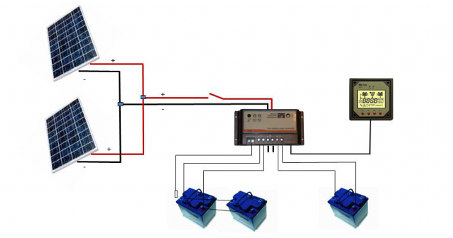 Wiring Diagram for a Two Solar Panel System, a Dual Output Solar Controller and Two Battery Banks
We are often asked questions about how to wire a solar system. This can appear to be a daunting task for those new to the world of solar but it is actually quite easy and straight forward. In this blog I will walk you through the wiring process for our dual output controller step by step. First, the definition of a few terms: The wiring diagram below is taken from our dual output controller manual and illustrates the basic wiring required for a two panel system, a dual output controller and two battery banks. Most solar controllers are single output so charge only one battery bank. In this case, it is common to wire the positive wire to the common on the battery 1-2-both battery switch to select which battery bank is to be charged.
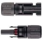
* MC4 Connector - A water proof connector used in solar wiring. Most solar panels come with MC4 connectors attached to 3 foot solar wire pigtail coming from the panel junction box. These connectors are easily disconnected.
* Solar Controller - Except for small trickle charge systems, all solar systems should have a solar controller. The purpose of a controller is to prevent batteries from being overcharged, apply the optimal charging current to the battery bank and prevent current from back flowing from the batteries to the solar panel at night. Controllers are sized by their amperage capacity. Controllers designed for residential and commercial (lighting) use are generally overkill and not well suited for marine applications.
* Temperature Sensor - This device is connected to the controller and senses the temperature of the battery bank. If the batteries are heating up due to heavy charging, the sensor signals the controller and the controller reduces the charge current appropriately. A temperature sensor is only useful for systems with larger solar arrays as smaller solar systems do not provide sufficient power to over heat the batteries.
* Solar Wire - While most any wire can be used in a solar system, solar wire is designed for maximum conductivity and is well insulated with a UV resistant cover. It is typically single conductor and the insulation is .25 Inches in diameter.
A few things to note in the diagram:
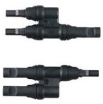
* The two solar panels are wired in parallel using an MC4 T-branch connector, If one panel is shaded, the other panel will still provide full power to the controller.
* There is a switch in the positive wire between the solar panel and the controller. This is optional. The purpose of the switch is to turn off the panel should it interfere with the alternator output when the auxiliary engine is generator is running. It has been reported that some smart regulators are confused by the power coming from the solar panel. It sees the sum of the battery charge plus the panel output and senses the batteries are fully charged so goes into float mode prematurely. This is easily remedied by flipping the switch thus disconnecting the solar panel.
* The optional temperature sensor is shown to the left of the larger house battery bank. It is simply taped on to the top of the battery.
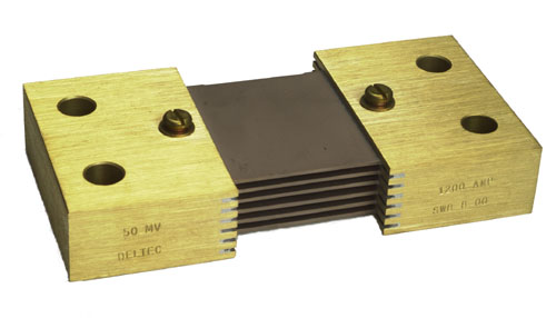
* If you have a battery monitor such as a Link or Xantrex 1000 or 2000, it is important to connect the negative wires from the controller to the shunt of the battery monitor. Otherwise, the monitor doesn't see the power coming in from the solar panel and will give inaccurate readings.
* There is a sequence to follow in connecting the solar system. Connect the controller to the battery banks first. Then connect the solar panel to the controller.
| | A Set ofMC4 T-branch Connectors | Cross Section of Solar Wire Illustrating Insulation Layer and UV Protection Layer | Example of a Battery Monitor Shunt |
Draw A Diagram Of Our Solar System
Source: https://www.custommarineproducts.com/blog/wiring-a-marine-solar-system
Posted by: guntergeopenceed.blogspot.com


0 Response to "Draw A Diagram Of Our Solar System"
Post a Comment